1. Overview
A mounted rotary tiller is a core tillage implement used with tractors. It consists of the frame, gearbox, blade shaft, rotary blades and the three-point hitch mount. Working conditions are harsh, so the drivetrain assembly accuracy, blade shaft coaxiality and bolt tightening reliability all carry high requirements.
In a conventional fixed-station setup, workpieces are moved by overhead lifting equipment, positioning is difficult, drivetrain assembly accuracy is hard to hold, quality data cannot be traced, and changing between machine models drags down efficiency.
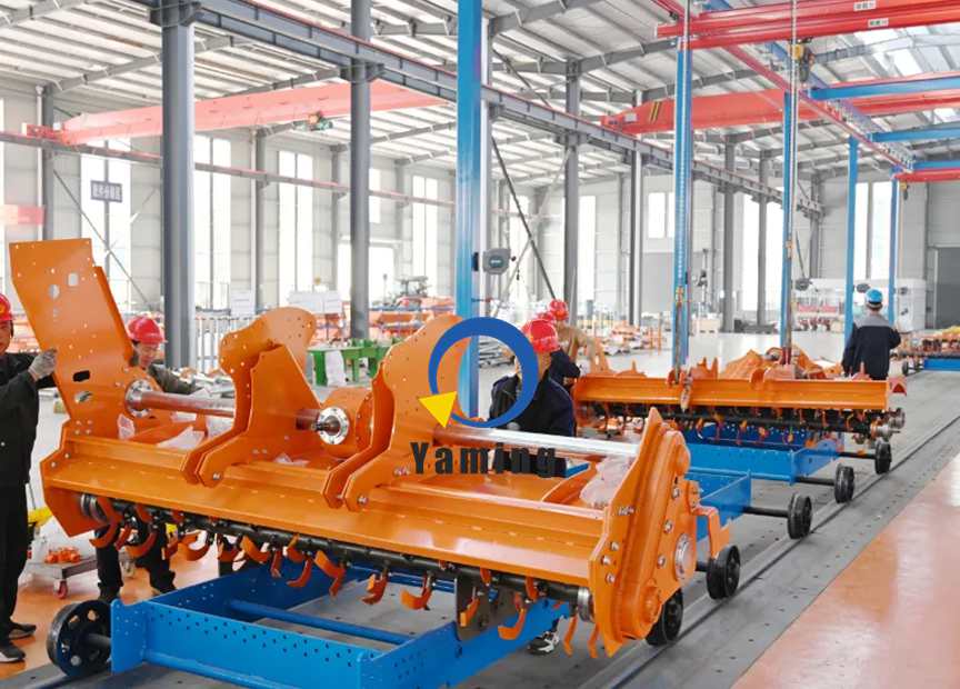
This rotary tiller production line uses a floor-mounted steel rail with circulating work trolleys as the transport system. Each trolley carries adjustable clamping fixtures, so the tiller frame is locked and positioned once it comes on line. The trolleys move in a pulsed (indexing) rhythm, carrying the tiller through frame pre-assembly, gearbox assembly, blade shaft and blade installation, hitch assembly, component inspection, final verification and off-line transfer — a complete rotary tiller assembly line.
The line is built from the steel rail track, circulating trolleys, frame clamping fixtures and the drive control system. Each trolley has a self-locking clamp with adjustable travel, so the frame stays stable with no shifting during assembly. Stations are fitted with hoists, servo tightening tools, inspection fixtures and parts racks. A station terminal with a barcode scanner ties each tiller to its serial number and records key tightening torques and assembly dimensions for full traceability. The fixtures are quick to adjust, so the line can run different tiller widths in mixed production — suited for new tiller assembly workshops or upgrades to existing plant floor.
The line addresses the common problems of awkward implement handling, unstable positioning and missed checks on critical steps, and prevents drivetrain noise, blade shaft deviation and loose fasteners before they become defects. The pulsed rail-trolley transport decouples station cycle times, so a stoppage at one station does not stop the whole line, and the production rhythm stays steady.
2. Assembly Process
The rotary tiller production line uses rail-trolley pulsed transport, with work trolleys circulating along the floor steel rail:
- Load and clamp station — the tiller frame is lifted onto the trolley, the fixtures clamp and lock it, the operator scans the machine serial number, and the trolley moves to the next station.
- Frame pre-assembly station — mount the hitch lugs and side plate supports to complete the frame base positioning.
- Drivetrain assembly station — install the main gearbox, connect the power input shaft, torque the critical fasteners with a servo tool, and record the torque data.
- Blade shaft and blade assembly station — assemble the blade shaft, install the rotary blades, and check blade shaft coaxiality.
- Accessory assembly station — fit the guard, depth wheel, hoses and labeling parts.
- Machine inspection station (core station) — check drivetrain clearance and fastener condition, verify blade shaft rotation, and look for interference.
- Final inspection station — review overall finish and re-check dimensions; the system marks the machine as pass or fail.
- Unclamp and off-line station — acceptable machines are unclamped and lifted off; failed units stay on the trolley for rework and return to the inspection station; empty trolleys cycle back along the return rail to the load station.
The key advantage of the rail trolley plus clamping fixture: the frame stays firmly fixed through the whole assembly, which makes heavy drivetrain parts easier to align and fit, while the circulating trolleys support mixed production across different tiller widths.
3. Customizable Parameters
The rotary tiller production line is a pulsed tillage-implement assembly line. The rail track, trolley bodies, clamping fixtures and inspection modules can all be built to order around the tiller’s dimensions, total weight and required cycle time:
- Transport system — heavy-duty floor steel rail, circulating work trolleys, variable-frequency pulsed drive; line length and number of stations are planned to production capacity, in straight or loop track layouts.
- Trolley clamping fixtures — each trolley carries pneumatic/hydraulic clamps with adjustable travel to suit different frame widths; the clamps have self-locking protection and controllable clamping force to avoid deforming the frame.
- Electrical and data collection system — station operator terminals, barcode scanners, serial-number binding, and recording of tightening torque, assembly dimensions and inspection values; process interlock and audible/visual alarms, with data logging for traceability.
- Integrated inspection modules — optional servo tightening units, drivetrain clearance check fixtures and dimensional verification devices.
- Line safety structure — safety guards, emergency stop interlocks at every station, limit bumpers at both track ends, and overload protection on the trolleys to prevent fixtures from releasing unexpectedly.
- Model expansion — quick adjustment of clamp travel to run different tiller widths, plus stubble-clearing implements and other rear-mounted tillage tools in mixed production.